Best of RoboFiesta – Originally published April 2024
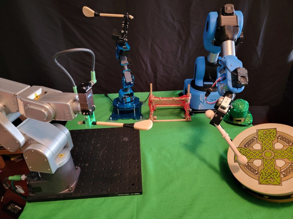
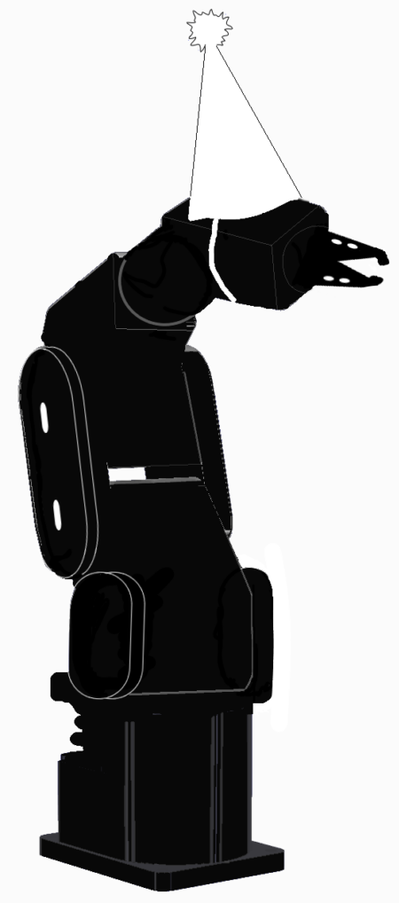
Especially a robot with the exceptional precision & control of the Mecademic 500.
This was just a short trial run, me basically playing around to see if:
- It was possible to create a robotic motion which played or “plucked” the tines to produce a tone similar to what is made when a human finger plays the keys, and
- The movement of the robot with “safe” position between tines / keys would allow for reasonable pace / rhythm in a short practice tune.
The first kalimba I tried is a nice basic unit with lovely tone, it’s been a lot of fun as an introduction to the instrument.
You can check it out on Amazon here: 17 Key Kalimba
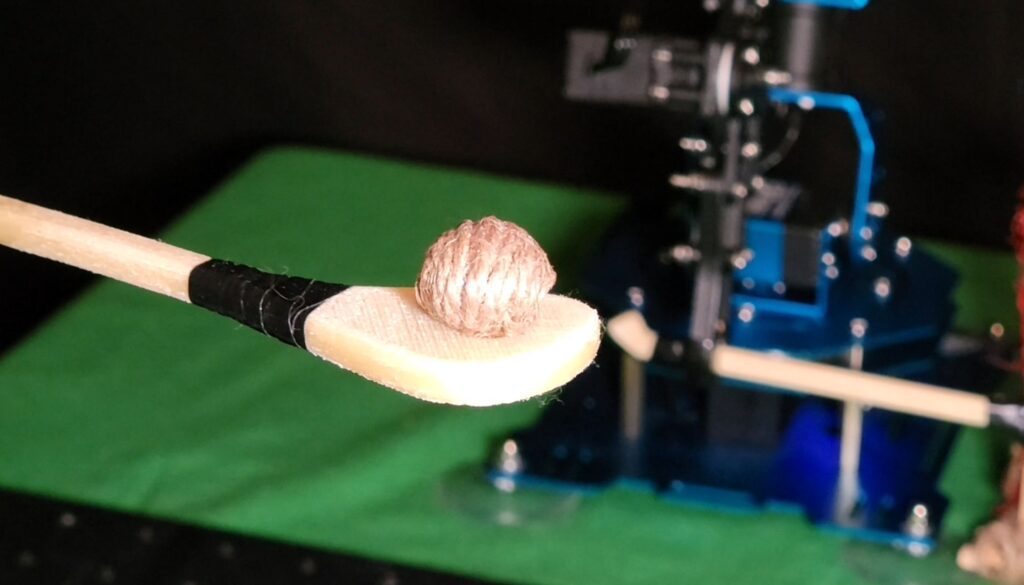
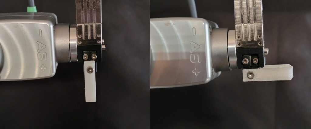
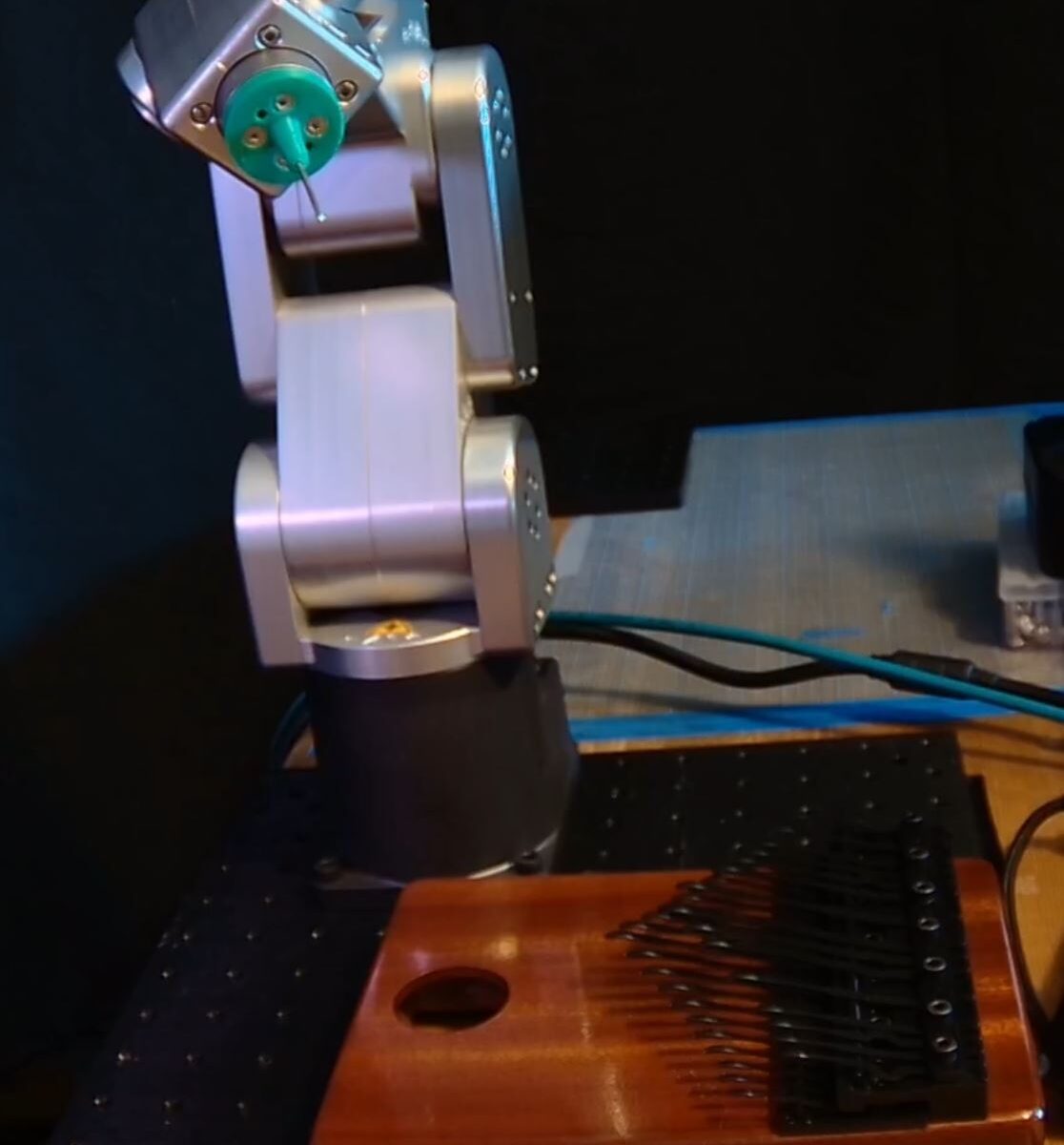
I found that, though not a problem for humans, the tines required a bit too much force for the robot end effector. The 1.5mm aluminum probe tip kept bending after a few keystrokes.
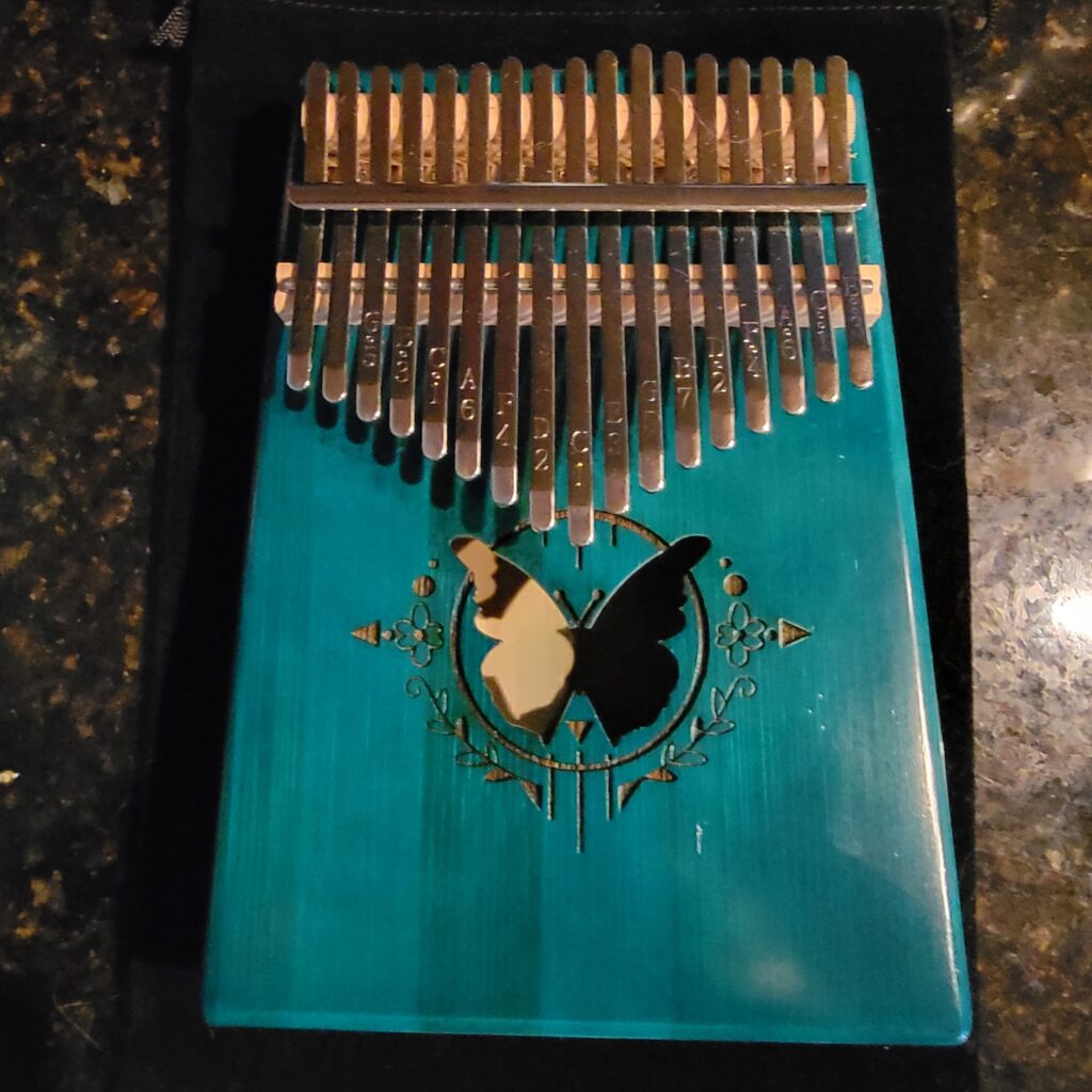
A little searching online found another type of kalimba, this one with a specialized key design that required a lighter touch. It also came in more than 1 variety, with different numbers of tines.
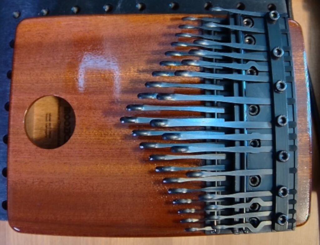
This kalimba is more polished / professional; I purchased one from Amazon with 2 day delivery: MOOZICA 36 Keys Chromatic Kalimba
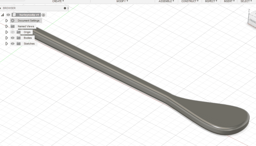
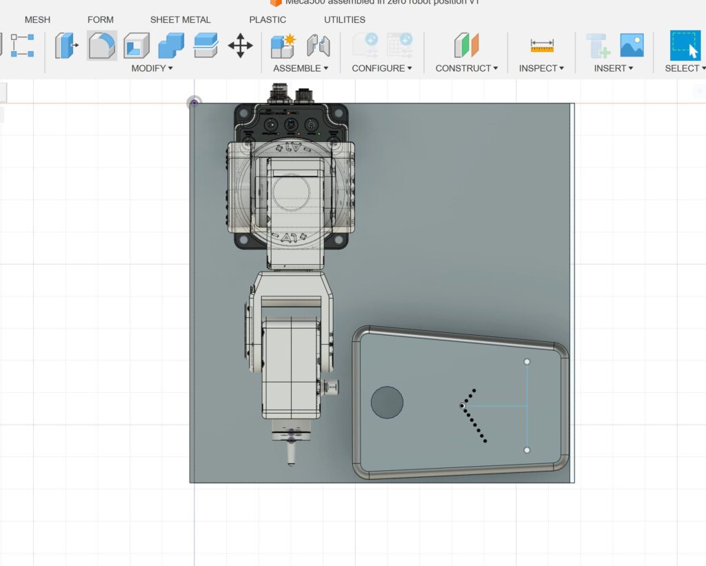
There wasn’t a ready-made .stp file or any CAD available for the kalimba, so I improvised in AutoCad Fusion to make a basic stage layout:
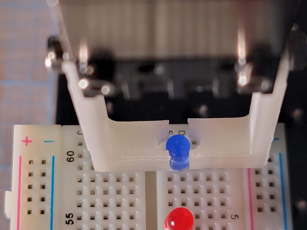
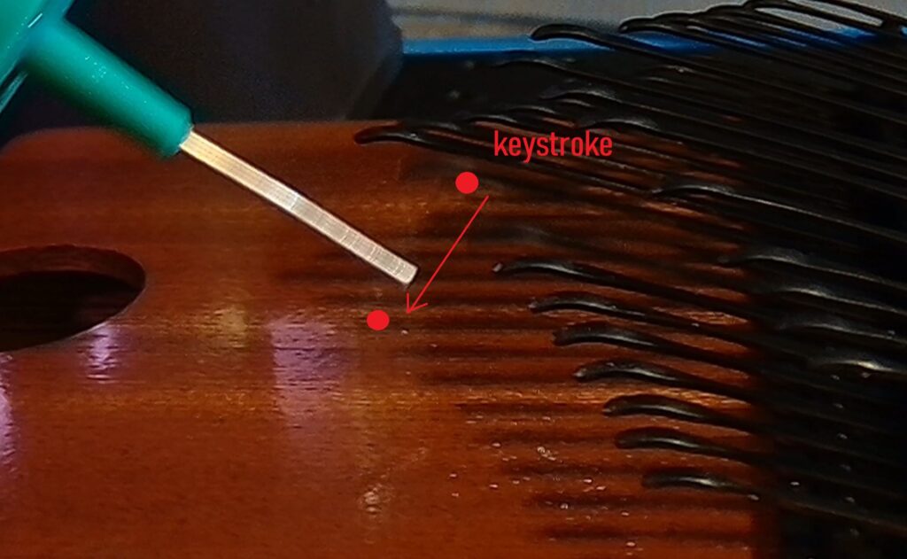
The tines are smaller and more rounded than the first kalimba, which made precision end effector placement & motion critical to tone. Just moving the EOAT vertically in a short rapid motion didn’t work; there needed to be a diagonal component, effectively “sliding” the probe tip off of the tine in a particular manner.
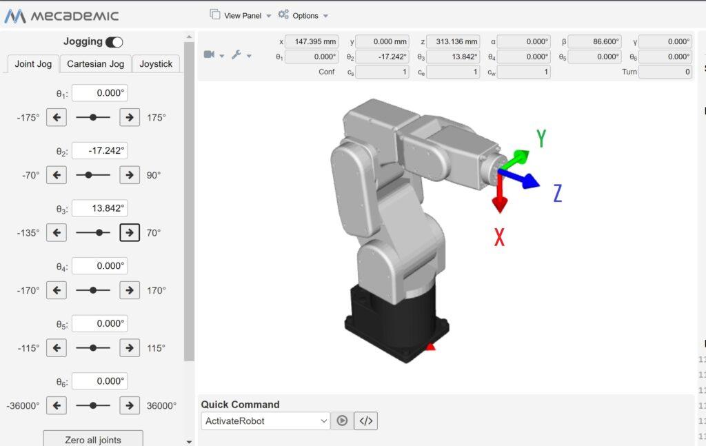
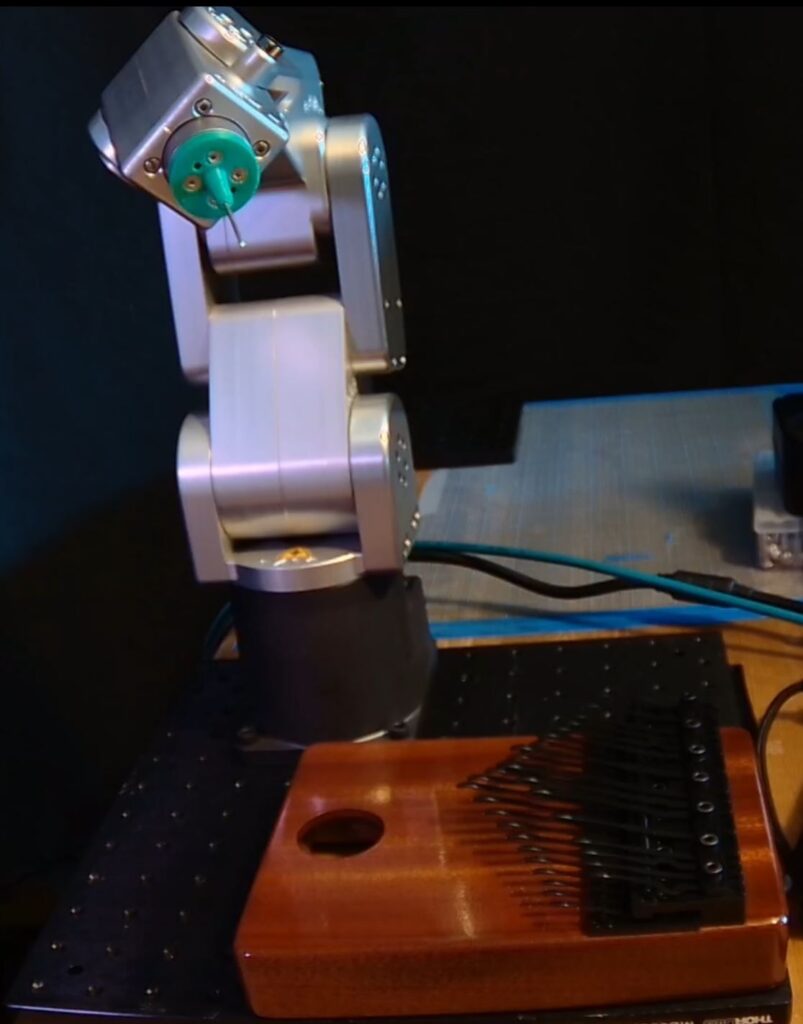
The robot motion was a sequence of move-to positions with some speed changes and delays to produce the timing of the tune. The move-to-safe motion is larger than it really needs to be, but I was concerned about clearances as I moved the blending values higher for smoother / more rapid motion. This is the code I programmed for the short video sequence:
I am working on a better CAD model of a kalimba, with the tines placed accurately. The whole stage could then be imported into a simulator like RoboDK to teach songs or melodies quickly. I did this one by eye, experimenting with different positions & motions to produce the best tones.
You can watch the YouTube video here: Mecademic Meca 500 Kalimba Concert 1
Product Links:
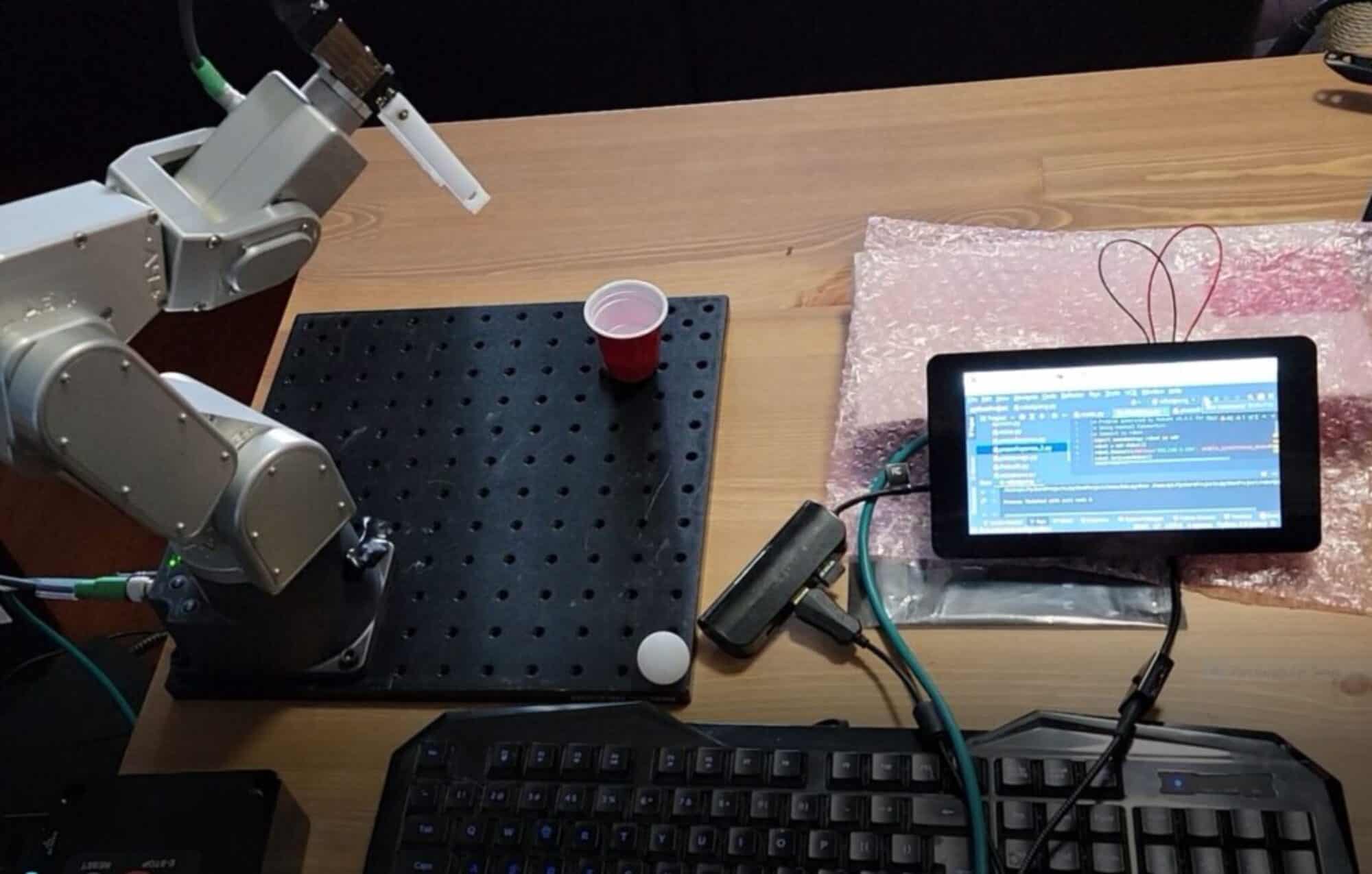
Robot stage
Optical Plate Flat Aluminum Honeycomb Breadboard: https://amzn.to/4aKMuYR
3D Printer
We highly recommend the Flashforge line of 3D printers for printing your robotic EOAT and staging parts:
FLASHFORGE 3D Printer Guider II Large Size Intelligent Industrial Grade 3D Printer https://amzn.to/3VKaGGA
FLASHFORGE Guider IIS 3D Printer Auto Leveling with High Temperature Nozzle https://amzn.to/3xpxJMF
FLASHFORGE Adventurer 5M Pro 3D Printer with 1 Click Auto Printing System https://amzn.to/3TQxYYz
FLASHFORGE Adventurer 5M 3D Printer with Fully Auto Leveling
https://amzn.to/3TMprpS
FLASHFORGE 3D Printer Adventurer Series with Auto Leveling with Quick Removable Nozzle https://amzn.to/3PSmeDO
Disclaimer: As a participant in the Amazon Affiliate program, we earn a small commission if you make a purchase through one of these links, at no additional cost to you.